COMPLETE SYSTEM
Basic Theories of Operation
These components are part of the CAN bike system communication (components ‘talk’ to each other):
- (MasterMind) TCU (can be seen as the master of the bike, also allowing external communication; fully identical to the first gen. TCU and interchangeable)
- Motor
- Batteries (Internal and/or Range Extender)
(Speed Sensor and remote act as switches and are not part of the bike communication as such)
This happens when display is switched on:
- Switch in (MasterMind) TCU closes wakeline
- Wakeline activates battery (wakeline goes from TCU to battery)
- Battery sends 48V to motor and 12V to TCU (12V come directly from battery)
- (MasterMind) TCU starts, LEDs light up (even if motor is not connected)
- SL system is active
Note on role of RE battery:
- The Range Extender battery can fulfil the same function as the internal battery (send 12V to display to start-up the system; also part of CAN communication)
- If an SL bike does not turn on, most likely the internal battery cannot supply its 12V – then a RE battery can be used to check if it really is the internal battery or the connection main harness-battery inside the frame – this is one example how to use the RE for troubleshooting
Difference versus Levo/Kenevo Gen2/3
In in a SL bike, the display also starts without a connected motor (‘motor not found’ on TCU), whereas the TCU of a Levo/Kenevo2 would not power on with a disconnected motor.
Mission Control: it is not possible to connect with Mission Control App when motor is not found or disconnected. MC would state that bike is switched off.
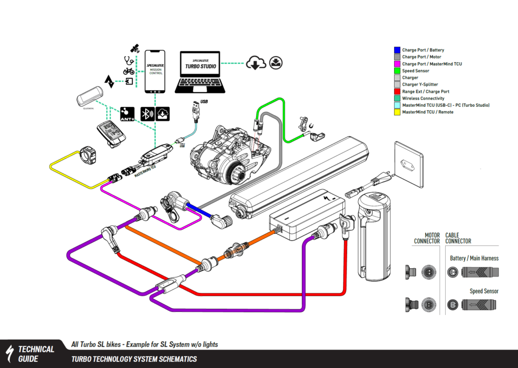
In red circles: components that are part of the CAN communication (they communicate and exchange messages)
In white circles: components that act as switches only (they give signals)

Full System Diagrams
These diagrams show the interplay of all SL components as a full system, including the communication to ecosystem tools through Bluetooth, ANT+ or cabled USB connection. (Mission Control App, Turbo Studio, ANT+ devices).
There are only minor differences between the systems as used in the different Turbo SL families (e.g. light integration, type of speed sensor magnet, remote).

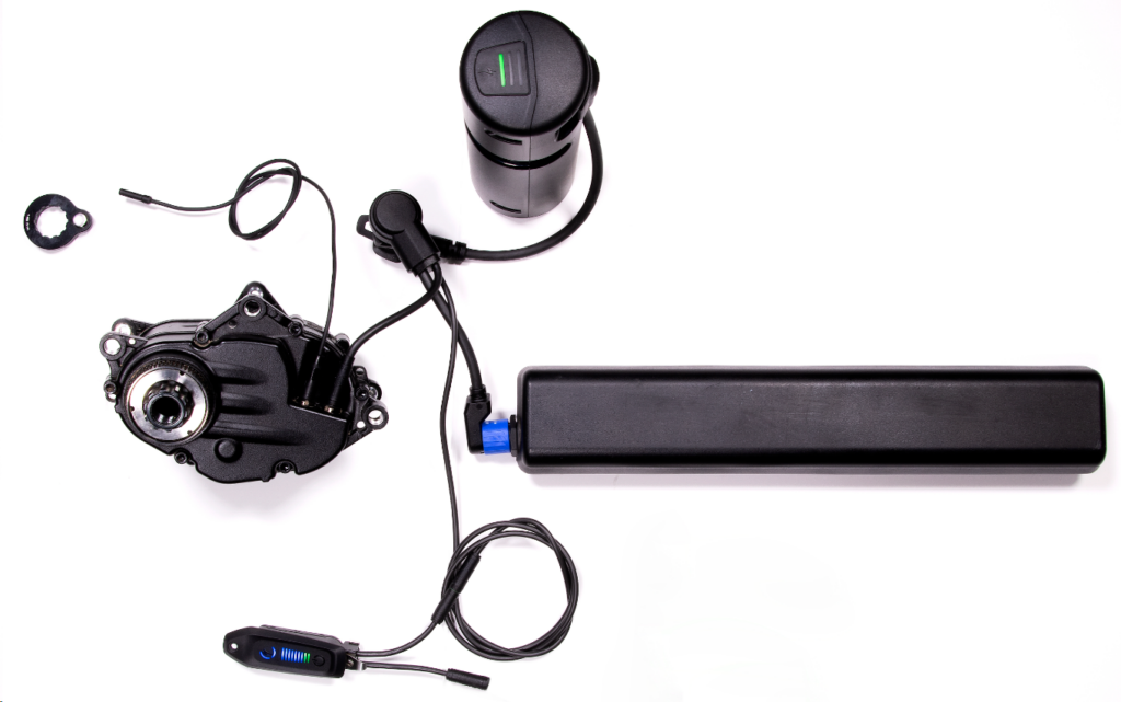
Desktop Setup
A so called « Desktop Setup » not only shows how the components are connected, it also helps test and diagnose parts.
A desktop setup should be used:
- to identify faulty part
- to test new ones before installation.
Normal System Behaviour
When something falls under `normal system behaviour`, it operates as intended per design and therefore cannot be classified as an issue. One common example for typical normal system behaviour would be motor power reduction at lower charge levels. Besides behaviour patterns that apply to all bikes, there is system-specific or even bike-specific `normal system behaviour`. Therefore, the referenced overview is broken down into different categories.
Understanding and referencing `normal system behaviour` helps you to:
- Distinguish between normal behaviour and issues
- Explain normal behaviour to Riders together with some advice
- Prevent problems for daily use

Motor Power and Remaining Battery State of Charge
This section explains the correlation of remaining battery state of charge and motor power. The behaviour should be known to understand the working principles, recommend best practices and manage rider expectations.
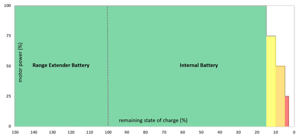
Simplified Power Reduction Table
It is normal system behaviour that between 15% and 20% remaining battery state of charge (soc), the system starts reducing motor support to ensure uninterrupted support at lower charge and voltage levels. The point of reduction depends on some variables such as battery combination, discharge sequence, current, voltage, cell temperature, start rsoc of each battery, etc.
| Battery combination / discharge sequence | Motor | Motor Power Reduction Based on Battery State of Charge (soc) Typical Cell Temperature Range (0°C – 50°C) | |||
| Discharging internal battery only or Discharging internal battery + Range Extender battery in parallel* | SL 1.1 and SL 1.2 | 75% motor power at soc 15% | 50% motor power at soc 10% | 25% motor power at soc 5% | 0% motor power at soc 3% (no motor support) |
| *Note for parallel discharge: As soon as one of the two batteries reaches the given soc values, power reduction will happen | |||||
| Range Extender first / only | SL 1.1 | 75% motor power at soc 20% | 50% motor power at soc 12% | 25% motor power at soc 7% | 0% motor power at 5% (no motor support) |
| SL 1.2 | SL 1.2: 70% of SL 1.1 values | ||||
Parallel Discharging or Internal Battery Only: Complete Motor Power Reduction Table
- Table takes battery temperature and rsoc into account (not motor temperature)
- Table refers to these two scenarios:
- Discharging internal battery only
- Parallel discharge mode (internal battery + Range Extender battery discharged in parallel as per default)
- RSOC = remaining state of charge
- RSOC refers to each battery separately when using an additional Range Extender battery
- The most common cell temperature spectrum is marked green
- Parallel discharge
- As soon as one of the two batteries reaches the given rsoc values, power reduction will happen. RSOC for individual batteries can be checked in Mission Control (tbd if also on MasterMind display)
- Point of reduction depends on some variables such as current, voltage, cell temperature, start rsoc of each battery, etc.
- The latest time the reduction would happen during parallel discharging is at 22% rsoc on the MasterMind display, following this calculation:
- Internal battery: 15%
- Range Extender battery: 7.5% (counts 50% on display)
- 15% + 7.5% = 22.5%
- Note that an earlier reduction is possible
| Temperature\RSOC | 100% | 20% | 15% | 10% | 5% | 3% | 1% |
|---|---|---|---|---|---|---|---|
| T < -20℃ (DUT) | 25 | 25 | 25 | 25 | 25 | 0 FD | 0 FD |
| T > 70℃ (DOT) | 25 | 25 | 25 | 25 | 25 | 0 FD | 0 FD |
| -20℃ <= T <= 0℃ | 75 | 75 | 50 | 25 | 25 | 0 FD | 0 FD |
| 0℃ < T <= 50℃ | 100 | 100 | 75 | 50 | 25 | 0 FD | 0 FD |
| 50℃ < T <= 70℃ | 75 | 75 | 50 | 25 | 25 | 0 FD | 0 FD |
Discharging Range Extender First: Complete Motor Power Reduction Table
- Table takes battery temperature and rsoc into account (not motor temperature)
- Table refers to discharging the Range Extender first (or discharging an RE only, which can be applicable)
- `RE first` is an option in Mission Control
- RSOC = remaining state of charge
- The most common cell temperature spectrum is marked green
- Compared to parallel discharge or discharging the internal battery only, power reduction happens earlier
Notes for below table:
- Values in table apply to SL 1.1 motor
- For SL 1.2 motor, deduct 30% of table values, for all soc levels that allow motor support
- SL 1.2 motor has about 30% more power than SL 1.1 motor and therefore, output of RE is limited with SL 1.2 motor. Examples:
- *max. motor power at soc 100% and normal cell temperatures is 70%
- **max. motor power at soc 20% and normal cell temperatures is approx. 50%
| Temperature\RSOC | 100% | 20% | 15% | 12% | 7% | 5% | 1% |
|---|---|---|---|---|---|---|---|
| T < -20℃ (DUT) | 25 | 25 | 25 | 25 | 25 | 0 FD | 0 FD |
| T > 70℃ (DOT) | 25 | 25 | 25 | 25 | 25 | 0 FD | 0 FD |
| -20℃ <= T <= 0℃ | 75 | 50 | 50 | 25 | 25 | 0 FD | 0 FD |
| 0℃ < T <= 50℃ | *100* | **75 | 75 | 50 | 25 | 0 FD | 0 FD |
| 50℃ < T <= 70℃ | 75 | 50 | 50 | 25 | 25 | 0 FD | 0 FD |
Discharging Internal Battery only or Parallel Discharging (SL 1.2 and SL 1.1 motor)
- Parallel discharging is the default when both batteries are connected – this is the recommended discharge scenario when rider uses a RE
- Advantages
- Rider gets best motor assist level over discharge spectrum, feels effect of motor power reduction as late as possible
- Gentle to range extender health
- If the two batteries are on different charge levels, the one with a higher state of charge will be drained first till voltage levels are equal; once equalized, the system switches to parallel discharging (unless Mission Control setting « Fully Discharge Extender Battery First » is active)

Discharging Range Extender Battery First
General
In the app you can change the default (parallel discharging) to define that you want to discharge the RE first.
- Requires bike system restart to be active
- At around 3% RE state of charge (= 103% with full internal battery), the system automatically switches to power supply from the internal battery to ensure smooth transition; these conditions need to apply for this to happen:
- « Fully Discharge Extender Battery First » was active until then
- Internal battery has more than 3% soc
SL 1.1 motor
Under normal motor/battery temperatures, riders will have 100% power from the beginning (RE charged to 100%); normal power reduction zones apply at lower state of charge.

SL 1.2 motor (RE only / RE first)
- Motor power is limited to 70%
- Under normal motor/battery temperatures, riders will have a 30% power reduction right from beginning (RE charged to 100%)
- This power reduction for SL 1.2 motors, when discharging the RE only, reflects the increased SL 1.2 motor power and ensures system stability over discharge
Common questions on « RE first »
When to activate « RE first »?
Generally, this option gives riders more flexibility and allows them to further improve bike handling if they continue their ride without the RE after it has been drained.
Benefits:
- For weight/handling reasons, rider wants to leave RE(s) somewhere for later pick-up after switching to internal battery
- Rider wants to make room for (additional) water bottle after RE discharge (e.g. carries [second] ]water bottle in backpack till RE is removed and water bottle can be put in cage instead)
Why to avoid discharging RE first?
Excessive use of this option may impact long term battery health as the RE cells experience more strain. Also, if rider wants best motor support throughout ride, batteries should be drained in parallel (voltage drop noticeable with delay).
What effect will a rider feel when choosing « RE first »?
General:
Discharging the RE first means that rider will more quickly notice less motor output because of a quicker drop in voltage (theoretically in half the time since RE only holds 50 % of the internal battery capacity).
In normal cell operating temperature (0 to +50°C), the power output is reduced when reaching a certain state of charge. This ensures uninterrupted motor support till motor shut-off. The point of power reduction not only depends on cell temperature, but also batteries used and the applied discharging logic.
SL 1.2 motor
- Motor power is limited to 70%
- Under normal motor/battery temperatures, riders will have a 30% power reduction right from beginning (RE charged to 100%)